Technical Info Download Contact

Instruments For Testing Your Innovations

Battery simulator, sometime is called battery emulator, is a very important equipment for testing battery chargers and battery-operated systems. Many portable electronic devices use rechargeable batteries such as lithium ion (Li+), lithium polymer, nickel metal hydride (NiMH), nickel cadmium (NiCd), or lead-acid battery. Many of these rechargeable devices have charger circuits built inside. For testing these electronic devices, a battery simulator or emulator is often needed. For example a lithium ion battery emulator can easily vary the voltage to simulate a battery is being charged or discharged. This eliminates hours of test time. A battery simulator power supply is great for bench testing as well as production testing.


To simulate a battery, a power supply emulates many of the battery’s characteristics. The most important characteristic is the ability to sink current when the battery simulator is charged. The battery charger drives charging current into a simulated battery. Therefore, the current is flowing into the simulator power supply. At the same time the simulator must able to source current seamlessly. In fact it must be able to transition between sink and source current without any glitches, even at high speed.

TS250/TS200 Battery Simulator/Emulator

The TS250 and the TS200 modulated power supply can mimic sink and source current the same way a real battery does. They feature a DC OFFSET knob that can adjust the voltage to emulate battery voltage changes. It’s especially useful for simulating a battery for charger circuit testing.

Conventional power supply cannot simulate a battery. It cannot sink current like a battery can. It is equivalent to a battery simulator with a blocking diode.

Figure 1. A) Simplified conventional power supply circuit. B) Equivalent circuit.

Battery simulator circuit is using two transistors. It can emulate a battery being charged. Battery simulator equivalent circuit model. It can sink and source current like a real battery.

Figure 2. A) Simplified battery simulator circuit. B) Equivalent circuit.

A B A B

Battery Emulator Applications

TimeBattery Voltage (Blue)Battery Current (Red)Battery Voltage (Blue)Battery Current (Red)End of chargeTrickle chargeCC ChargingCV charging4.2V

Figure 6. Lithium ion battery CC/CV charging profile.

Selecting a Simulator

Both the TS250 and the TS200 can simulate batteries. The TS250 has an additional feature for output current LCD display. Thus, it eliminates the need for external current monitor. Use the below table for selecting a simulator power supply.

Model

Voltage Range

Lithium Ion

NiMH/NiCd

Alkaline

Lead-Acid

TS250-4

-6V to +15V

1-3 cells

1-10 cells

1-9 cells

6V or 12V

TS250-5

-6V to +30V

1-7 cells

1-20 cells

1-18 cells

6V/12V/24V

TS250-6

-6V to +45V

1-10 cells

1-28 cells

1-25 cells

6V/12V/24V

TS200-4A

0 to +15V

1-3 cells

1-10 cells

1-9 cells

6V or 12V

Conventional power supply can only source current, but cannot sink current. Thus a conventional power supply cannot effectively simulate a battery. Figure 1 and 2 show simplified diagrams for the difference between a conventional power supply circuit and a battery simulator power supply. Conventional power supply circuit is depicted with a single NPN transistor allowing current to flow only in one direction – sourcing current. On the other hand, the simulator power supply can sink and source current as shown in Figure 2A. The top NPN transistor is for sourcing current and the bottom PNP transistor is for sinking current.


A simulator can easily change the “battery” voltage by adjusting a knob, compared to a real battery whose voltage is slowly changed by charging or discharging. Thus a battery simulator test equipment is very useful for testing battery-operated systems. Instead of waiting hours for the battery to charge or discharge, a simulator can emulate the battery voltage behavior in seconds. In summary, a simulator is ideal for bench testing, debugging chargers and production testing.

Battery Simulator Power Supply

Battery simulator connection diagram for testing a charger.

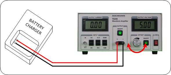
Figure 3 shows a typical battery simulator test equipment connection for testing chargers.

Infinite Capacity

A real battery has a finite capacity. When a battery is charged or discharged, its voltage is changing slowly. On the other hand, the battery emulator keeps its voltage constant. This is equivalent to a battery with infinite capacity or a very large battery. Battery simulator power supply with non-drifting voltage is ideal for bench testing. Especially, when you want the voltage to be constant for the duration (minutes to hours) of the test.


Simulate Source Impedance and ESR

A real battery has its own internal impedances called ESR (electric static resistance). When current is draw from the battery, its voltage drops slightly. ESR is calculated by the voltage drop (delta voltage) divided by the current. Figure 4 shows a simplified model of a battery ESR. Figure 5 shows how the battery simulator can add ESR to emulate a real battery. Typical ESR is the range of 0.1 ohm to 1 ohm and depends on the battery chemistry, capacity, temperature, age, and state of charge. The TS200/TS250 battery emulators have a very low output ESR, in the range of 0.05 ohm to 0.1 ohm. Add an external series resistor will simulate the ESR. Don't forget to account for connection wire resistance and contact resistance.

Battery ESR model using a resistor. Battery ESR is simulated using an external resistor.

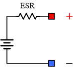
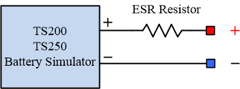
Figure 4. Real battery with internal ESR resistance.

Figure 5. Add an external series resistor to emulate battery ESR.

Battery Charger Testing

Most portable electronic devices have built-in charger that recharges the battery. During product development and final production testing, the charger circuit must be thoroughly tested to ensure its reliability and safely charges batteries. Figure 3 shows typical battery emulator/simulator connection for charger and system testing. It is basically replace the battery with an emulator. Use the Battery Simulator Quick Start Guide for setting up charger testing. A battery emulator is the most valuable instrument for battery charger testing.


Lithium Ion Battery Simulator and Testing

Battery emulator/simulator is often used to test the charger’s operation over the entire battery voltage range (e.g. 0V to 4.2V). For example, a lithium-ion battery’s normal operating voltage is 3.0V to 4.2V, but the voltage also can be 0V to 3.0V, if it is deeply discharged. Likewise a lithium ion battery can also be over charged to 4.3V – 4.5V. The charger circuit must be tested to ensure that it can charge a battery at any voltage within the limit. Using a simulator, you can easily simulate the battery at any voltage by adjusting the knob. You can measure the charging current at low battery voltage, less than 3V for Li+ battery, normal voltage 3V to ~4.2V, and high voltage greater than 4.2V, to verify against its specifications. While charging, adjust the lithium ion simulator knob to simulate the entire voltage range. Look for any unusual charging behaviors such as oscillation as you are charging.


Battery Emulator Advantages

Normally, it takes several hours to fully charge a real battery. For testing purpose, instead of waiting for the charger to charge a real battery, you can use a battery emulator to quickly vary the voltage to emulate the battery being charged. At the same time, you can observe and test the charger behavior to ensure it meets all of the specifications and safely charges the battery. Battery emulator power supply is important for charger circuit testing.


For example, lithium ion battery typically employed a CC/CV (constant-current, constant-voltage) charging method. At a low voltage, less than 3.0V, the battery is being trickle charged at a low current (one-tenth of the normal charging current). For voltage between 3.0V and ~4.2V, it is being charged at a rapid charging current. When the battery voltage reached 4.2V, it enters constant voltage mode where the voltage is held constant, but the charging current is slowly reduced. Figure 6 shows the detailed CC/CV lithium ion battery charging profile. An emulator is ideal for testing each phase of the charging cycle as well as testing transitions between phases. By adjusting the voltage knob, the battery emulator allows easy back-and-forth phase transition testing.

Multiple-Cell Battery Emulation

Another fundamental use of battery simulator/emulator is to emulate a series connected battery cells inside a battery pack. Various medium-power mobile systems utilize several battery cells connected in series inside a pack. These batteries are primarily lithium-ion or lithium-polymer. Some of the popular configurations are two, three, four, and six batteries connected in series. Serially connecting battery cells boosts the input voltage of the system and makes it possible to supply electrical power more efficiently. As a result of variations in voltage output from one cell to the next, it is possible that most of the battery cells within a pack may not be at the exact same voltages. In addition, there are cases in which one or more of these cells are damaged or broken. When charging a series connected cells, it is possible that some of the battery cells are undercharged and some cells are over-charged. For safety reason to prevent overcharge and without cell balancing, the charger design might deliberately under-charge the battery pack to prevent over-charging any of the batteries. Therefore, battery cell balancing is required to achieve the maximum battery capacity as well as retaining battery pack safety.


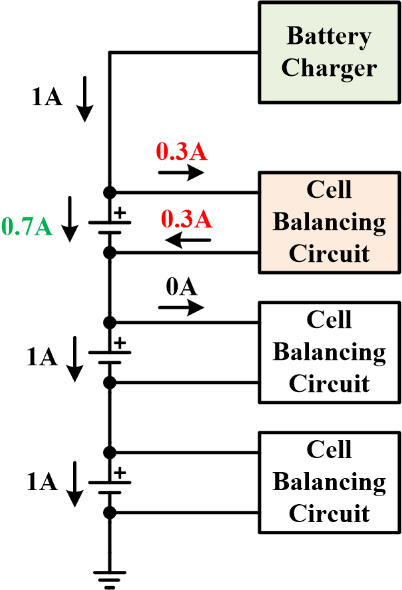
To understand how battery cell balancing work, refer to Figure 7. When one of the batteries approaches being fully charged, the active cell-balancing circuitry diverts a part of the current away from that specific battery while keeping a large charging current for the two undercharged batteries. That is, whichever cell is near full, the cell-balancing circuit reduces the charging current. The remaining cells will continue to charge at high current. As any of the cells approaches being full, the charging current keeps diminishing by the balancing circuit. This process is maintained on till all three of them are completely charged. Therefore employing cell balancing techniques will keep all battery cells fully charged.

Figure 7. Cell balancing circuit divert current away from nearly-full charged battery.

Battery Simulator

Ask Us Questions

Simulating a battery for easy charger testing using the TS200 modulated power supply.

Visit TS200 Page

Visit TS250 Page

This battery simulator test equipment is for testing chargers by varying the TS250 DC Offset voltage.

Click on the image to enlarge

Cell-balancing circuits manage battery current to keep all cells fully charged.

The charger and the balancing circuitry must to be completely tested throughout the entire design phase. To test the charger and cell balancing circuit design, use a battery simulator(s) to vary the voltage to emulate the cell voltage change. At least one battery simulator is necessary for verifying the cell balancing circuit, preferably use one emulator for each simulated cell. System test engineers can replicate a range of scenarios where the battery is out-of-balance in order to monitor the cell balance circuit behavior. As shown in Figure 8, all of cell-simulators can adjust its voltage individually. In this way, it is fairly easy to change each simulated battery voltage to imitate a battery cell that is undercharged, overcharged, completely-drained, full, or damaged. With these emulators, test engineers can easily mimic variety combinations of battery-cell states mentioned above (fully charged, overcharged, undercharged, or broken) to stress test both the charging circuit and balancing circuit.


The TS250/TS200 can act as cell simulator for testing cell-balancing design discussed above. Here are some example test cases. Vary one of the simulated battery is overcharged state (i.e. >4.2V), there shouldn't be any charging current to that particular cell. The rest of batteries are continued to be charged normally. If one of the simulated battery cell falls below the safe voltage level (for example, below 3 volts), the balance circuit should prevent the charger from start high-current charging. The charger should fold back to trickle charge. By simulated some cells are full while others are not, the balancing circuit should keep high charging to cells that are not full and little or no current to cells that are full. You can simulate a damaged cell by setting its voltage to 0V to see how the charger responds. As you can see, there are many combinations of cases and each one of them need to be bench verify.

Battery emulators connected in series to test charger and cell balance design.

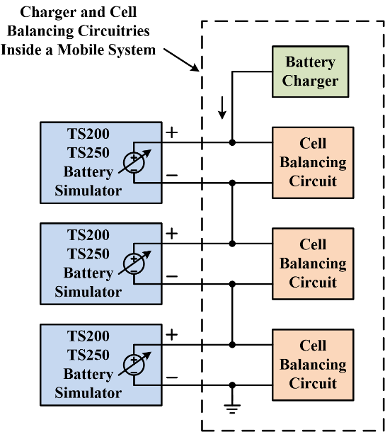
Figure 8. Battery simulators use to test charger and balancing circuit design.

PDF Version of this App Note

Related Technical Information

    Charger Design

    Four Quadrant Power Supply

    TS200 Simulator Quick Start Guide

    TS250 Simulator Quick Start Guide

Visit TS200 Product Page

TS250 vs. TS200

Visit TS250 Product Page

Ask Us Questions

Quick Links

Copyright: Battery Simulator
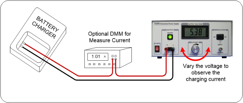
TS250 Price List

TS200 Price List

Batter simulator connection diagram using the TS200

Figure 9. TS200-4A battery simulator connection for testing a charger.

Request a Quote

Request a Quote