


Instruments For Testing Your Innovations


Piezo Amplifier
Piezo amplifier is ideal for driving high-capacitance and high-frequency piezoelectric devices. Piezo actuators and transducers are usually capacitive. Due to their high-capacitance, their impedance is low at high frequencies. A high-current amplifier is needed to drive them at ultrasonic frequencies. The amount of current required is calculated by Ohm’s law and it is proportional to voltage, frequency, and capacitance as shown in Equation 1. In Equation 1, I is the current, V is the voltage, C is the piezo capacitance, and is the angular frequency.
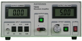
Figure 2 and 3 illustrates two examples of TS250 piezo amplifier high-frequency output voltage waveform. It can drive up to 80Vpp sinewave at 2.7A or 40Vpp at 4.4A.
Figure 1. The TS250 piezo driver amplified signal and drives a piezo transducer.
Piezo Amplifier Output Waveform Examples
Piezoelectric Amplifier Connection
Figure 2. TS250-3 generates 80Vpp 35kHz ultrasonic sinewave into 15 ohm load which is +/-2.7A current
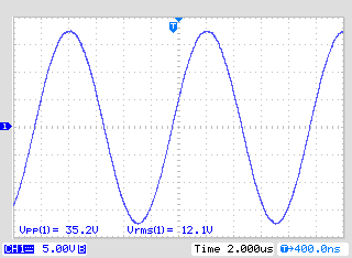
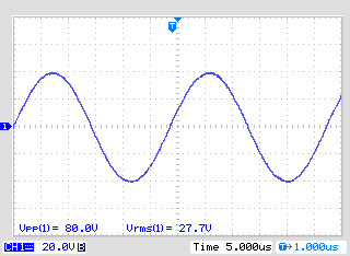
Figure 3. TS250-1 drives 100kHz 35Vpp into 3.9 ohm load (+/-4.4A).
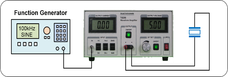
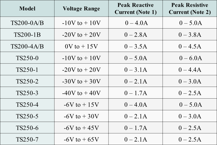
Table 1. Piezoelectric Driver Selection Guide
Piezo Driver Selection
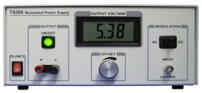
The TS250 and the TS200 are both high-current and high-voltage piezo driver. Unlike other amplifier instruments available today, the TS250 and TS200 are capable of output very high current at ultrasonic frequencies. Table 1 details the TS250/TS200 piezoelectric driver output voltage and current ranges.
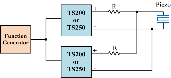
Figure 5. Connect two TS250 in parallel to increase the output current by 2x.


Related Technical Information
Note 1. Piezo element is capacitive which means their power is reactive. The TS250 output current is adjusted for reactive power.
Note 2. Peak resistive current is specified at maximum voltage minus 1V. For ex maple 19V for the TS250-1.
Driving Resonant Piezo Devices
High-Frequency Piezo Amplifier Impedance Matching
High-Voltage Piezo Driver
Some piezoelectric devices are operating only at resonant frequency. An example of these devices is Langevin Ultrasonic Transducers for ultrasonic washing and cleaning applications. At the piezo resonant frequency, these devices’ impedance are actually resistive as opposed to capacitive. These resonant pzt devices often specified operating power rather than voltage. For example, a resonant piezo transducer specified 16 ohm resistance at resonant frequency and the maximum operating power is 32 watts. The TS200 or TS250 ultrasonic amplifier can output up to ~70 watt.
To chose a piezoelectric amplifier, select the TS250/TS200 model that outputs the highest current using Table 1 above. The highest current is calculated by the piezo amp’s maximum voltage divided by the resonant resistance, or the peak resistive output current in Table 1, whichever is the lowest. For example, for a 16 ohm high-frequency piezo transducer, chose the TS250-2 (+/-30V). The maximum current is 30V/16ohm = 1.875A. The peak power is 56.25 watts (1.875A*30V = 56.25W). The RMS power is 28.1W. It is calculated by the RMS current times the RMS voltage (Equation 5). The RMS current is the RMS voltage divided by piezoelectric resonant resistance.
As discussed above, high-frequency piezo transducers and sensors are highly capacitive. Its impedance is nearly all reactive without real resistance. Such piezo devices does not dissipate real power. This means all power are dissipated inside the piezo driver instead. The result is in excess heating of the piezoelectric driver amplifier. The TS200/TS250 can dissipate about 45 watt RMS power.
Parallel Piezoelectric Drivers For Higher Current
The TS250-1 is able to output 3.1A peak current for driving piezoelectric device. To increase the piezo driver output current, two or three TS250/TS200 may be connected in parallel. As shown in Figure 5, each ultrasonic piezo amplifier driver is isolated with a small series resistor. The resistance is typically between 0.25 ohm to 1 ohm. Contact factory for more information on parallel connection and high output current driver.
Reactive Power vs. Real Power
One simple technique to increase piezo driver output current is to make the high-frequency pzt device more resistive. It can be done by just adding a resistor in series with the transducer as shown in Figure 4. The resistance should be chosen between 0.5Z to Z. Z is equal to the piezo transducer’s impedance. For example, if the transducer impedance is 20j ohm at 10kHz, chose the series resistor between 10 ohm and 20 ohm. The total impedance is now equal to Equation 2 below. The power dissipated in the matching resistor is given in Equation 3. The dissipating power can be very high and the resistor may be hot. Be sure to select the impedance matching resistor that handles the power.
Increase Resistive Impedance
Bipolar vs. Unipolar
Some high-frequency piezo motors, actuators, transducers required bipolar voltage. This means that the applied voltage swing between negative and positive. For example, the voltage across the actuator is a sinewave with an amplitude -20V to +20V. On the other hand, some piezo devices only need unipolar voltage or only positive voltage. An example would be a sinewave swinging from 0V to +40V. Table 2 shows voltage ranges of the TS200 and TS250 piezo amplifiers.
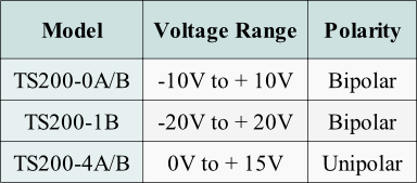
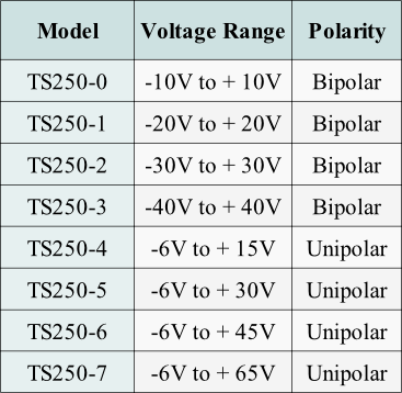
Table 2. Piezoelectric Transducer Amplifier Selection Guide
The TS250 outputs up to 65V. If higher voltage is required, an isolated DC power supply can be used to boost the voltage higher. For example a unipolar piezoelectric actuator needs a DC bias voltage of 100V and a 80Vpp sinewave. The operating swing voltage range is from 60V to 140V. Using an isolated DC power supply in conjunction with the TS250 piezo driver can generate extremely high power (reactive or real) and high current.
As shown in Figure 6, the piezoelectric amplifier driver is connected in series with the DC power supply. The combination of the function generator, Waveform Amplifier, and DC supply, formed a high-voltage function generator. Make sure the TS250 driver negative output terminal is connected to ground. The ground connection is common with the function generator ground and the piezo load. Most DC power supplies already have capacitors internal. It is still recommended to add external bypass capacitors, especially for high frequency piezo. You may use multiple capacitors connected in parallel. It is recommend to use low ESR and ESL ceramic capacitors, but a mix of electrolytic, tantalum, and ceramic caps are acceptable. The total capacitance should be large enough such that their impedance is much lower than the pzt load impedance.
For example, if the high-frequency piezo actuator capacitance is 3.3uF, the peak voltage required is 20V, and the frequency is 10kHz, the required peak current is 4.14A. A very high-current piezo driver is needed to be able to drive that much current. Higher frequency often requires an even higher current.
Other than high current, piezoelectric actuators also require high voltage. Their operating voltage range is generally greater than 10V and can go up to 100V or more. Most signal generator such as those waveform generators are less than 5V, but piezo elements require higher voltage. Therefore a high-voltage and high-current piezoelectric amplifier is needed for driving them. For instance, a piezo motor requires an 40Vpp waveform, but a function generator output is only 5V. As shown in Figure 1, the TS250 is acting as a signal generator amplifier and outputs high-current and high-voltage sine-wave that drives the piezoelectric sensor. Basically, the TS250 high current amplifier functions perfectly as a piezoelectric amplifier and driver.
High-Voltage Piezo Driver

Figure 4. Simple resistive impedance matching increases the piezoelectric driver output current.

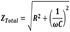

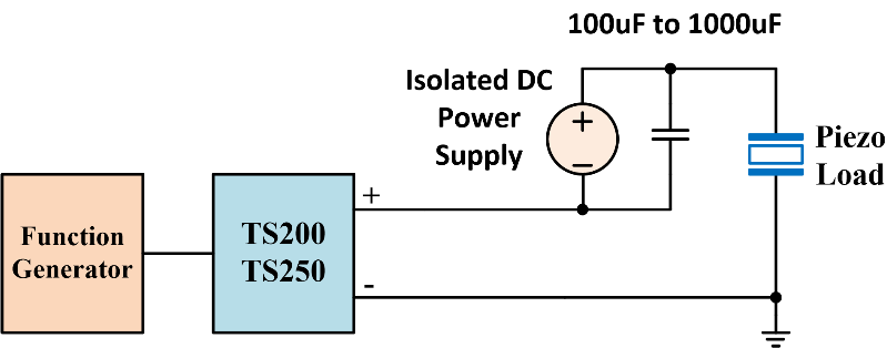
Figure 6. Using a piezo amplifier and a DC power supply for high-voltage testing.


Copyright: Piezo Amplifier


