


Instruments For Testing Your Innovations


Generate high-
Using classic series resonant to generate magnetic field can partially solve the above problem by lowering the impedance and therefore lower the amplifier driver voltage requirement. However the maximum current is limited by the AC magnetic field generator amplifier driver output current capability. The new resonant circuit discussed below will further increase the coil current by 2X.
AC Magnetic Field Generator Uses New Resonant
Figure 3. Classic resonant circuits (a) series resonant tank. (b) parallel resonant tank.
Table 1. Waveform Driver Amplifier Selection Guide
Section 1:
Why High-Frequency AC Magnetic Field Generation is Difficult
Figure 2. New resonant circuit doubles the amplifier output current achieving high frequency and high magnetic field.
To generate high-
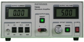
To generate alternating magnetic field, a waveform amplifier is needed to drive the resonant circuit as shown in Figure 2. The function generator produces a sinewave. The sinewave is amplifier by a driver amplifier such as the TS200 or the TS250. It can amplify the function generator voltage or current or both. The waveform amplifier is driving a large current into the current-
The series resistance R is optional. It is for better impedance matching. See Maximizing Amplifier Output Current application note for details how to choose the optimal resistance. In general the series resistor can be omitted.
Figure 1 shows the new resonant circuit. It is consisted of two equal value capacitors, labeled C, and a magnetic coil. At resonant the magnetic coil current is twice as much as the input source current from any amplifier. Section 2 below discussed the mathematical theory behind the current amplification.

Current-Amplified Resonant
Figure 4 is showing the new current-
Newly Discovered Current-Amplified Resonant Circuit

Figure 1. New resonant circuit doubles the magnetic coil current and magnetic field.
Section 2:
Understand the New Current-Amplified Resonant
The classic series and parallel LC resonant circuit have been used in numerous applications such as oscillators and filters. LC resonant tank can also be used for magnetic field generator. A new resonant circuit is studied in this App Note for the purpose of generating high-
Classic LC Resonant Circuit
Figure 3 shows the series and parallel resonant circuits. The series LC resonant tank features low impedance at resonance. The coil impedance is canceling the capacitor impedance. Thus achieving low impedance enables high current through the LCR circuit. Up to now, the most practical and efficient way to drive high current through magnetic coil is using series resonant circuit. Thus series resonant technique is often used for high-
The parallel resonant circuit on the other hand, its impedance is maximum at resonance. At resonant the current is resonating between the coil and capacitor. The current passing through the magnetic coil is very high while the source current is very low -


Figure 4. Novel current-
Finding the Resonant Frequency
To calculate the resonant frequency, first we need to define the resonant conditions. The requirements for resonant is such that at a given frequency the imaginary (reactive) portion of the input impedance, Z, is equal zero. The impedance is purely resistive at resonance.

In Figure 4 the electromagnetic coil resistance is usually small value and parasitic to the coil. The small resistance has no measurable effect on the tank resonant frequency. To simplify the resonant frequency calculation, the small resistance is excluded. In general magnetic coil with small resistance is better for high strength magnetic field generation. The two capacitors forming the resonant circuit are the same value (CS = CP = C). Looking at ZP only, it is a classic parallel resonant. Using equation A3 from the Appendix section below, the imaginary portion of ZP is given in Equation-
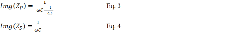
Now substitute Equation-
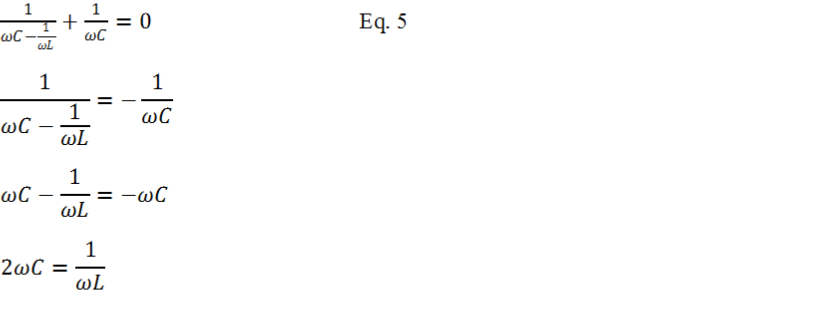
Next is solving for frequency ω. The result is showing on Equation-
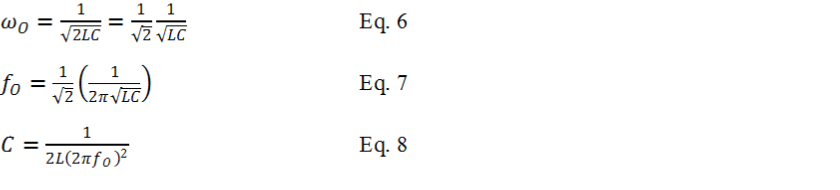
Remember ωo=1/√LC is the classic (series or parallel) resonant frequency of Figure 3. Rearranging Equation-
How Resonant Amplifying Current
As mentioned above, the new current-

Figure 5. KVL and KCL are used to calculate the electromagnet coil (inductor) current.

Remember from Equation-

From Equation-
To further rearrange Equation-
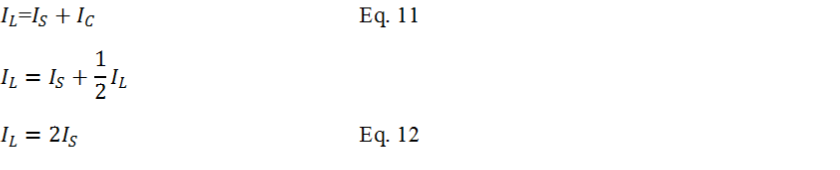
In conclusion from Equation-

Figure 6. Visual depiction of the magnetic coil current is two times the source current.
Resistance at Resonant
To understand the impedance of the resonant tank circuit, consider the reactive (imaginary part) impedance Z is zero as previously mentioned in Eqation-
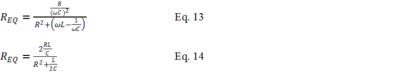
Because the L/(2C) term is much bigger than the R2 term, The R2 term is ignored. Equation-

From Equation-
The Q of the Tank
The main topic of this study is the novel resonant circuit’s ability to magnify the input current by a factor of 2 for free. The boosted current is ideal for generating high magnetic field density. From the above equations, the quality factor Q does not impact the current amplification. To complete the new resonant study, the quality factor Q is presented here.

Figure 7. For calculating Q, the current-
Recall the small-

In conclusion the new current-
Section 3:
High-Frequency Magnetic Field Generator Test Results
SPICE Simulation
The current-
In the SPICE simulation, the coil resistance was set to 125mΩThe simulated source voltage was set to 2.5V. The measured source current is 5A. The calculated resonant tank effective resistance is 500mΩ As discussed above the resonant circuit transforms the coil resistance by a factor of 4. Simulation confirms Equation-
When the source generator current vs frequency is plotted in Figure 10, it reveals two resonances: the new resonant and the classic parallel resonant. The current-

Figure 8. Current-

Figure 9. The new resonant frequency is found by the magnetic coil current vs frequency.

Figure 10. The new current-
AC Magnetic Field Generator Experiment Results
An experiment was designed to use a real coil (inductor) to confirm the current -

Figure 11. TS250 Waveform Amplifier used to generate high frequency magnetic field.
The first step is to set the function generator and the TS250 amplifier driver to the calculated resonant frequency (112.5kHz) with a 10Vpp sinewave. Next find the resonant frequency by slowly adjust the frequency until the coil reaches maximum current. The resonant frequency was found to be 116.5kHz. Now slowly increase the magnetic coil current by increase the TS250 peak-
Using Equation-


Figure 12. 3App input source current is measured across R2. 1V = 1A.
Figure 13. 6App magnetic coil current is measured across R1. 1V = 1A.
Current-Amplified Resonant Conclusion
The newly discovered current-

Related App Notes
High-
High-

PDF Version of this App Note
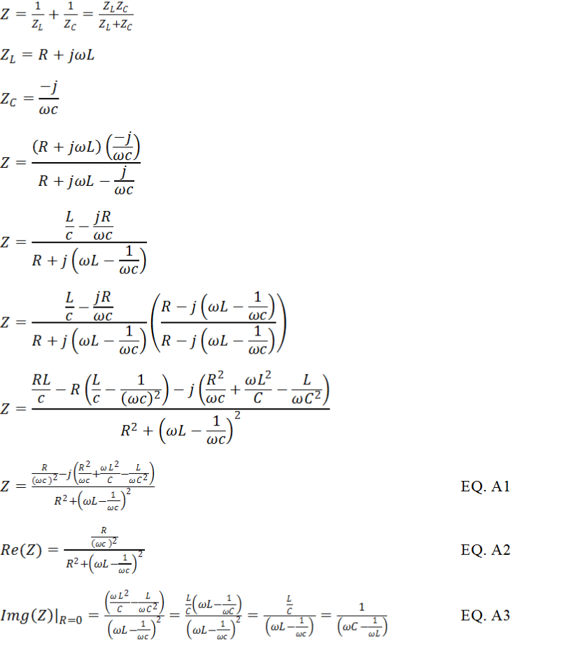
Appendix – Parallel Resonant Impedance Derivation

Figure A. Classic parallel resonant circuit consisted of RLC for calculating impedance and reactance.
Section 4:
Coil Amplifier Driver Selection Guide
As shown in Figure 2, high-
|
Waveform Amplifier |
Voltage Range (V) |
Coil Resistance (Ohm) |
Resonant Resistance (Ohm) |
Peak Amplifier Current* (A) |
Peak Coil Current* (A) |
|
TS250- |
- |
0 to 0.3 |
0 to 1.25 |
- |
- |
|
TS250- |
- |
0.3 to 1.0 |
1.25 to 4.0 |
- |
- |
|
TS250- |
- |
1.0 to 2.25 |
4.0 to 9.0 |
- |
- |
|
TS250- |
- |
2.25 to 8.8 |
9.0 to 35 |
- |
- |
|
TS200- |
- |
0 to 0.38 |
0 to 1.5 |
- |
- |
|
TS200- |
- |
0.38 to 1.1 |
1.5 to 4.5 |
- |
- |

Custom-Made Coil Information
50mm diameter High-
207mm diameter Helmholtz coil pair for generating 20mT
We offer custom-made coils to meet our client’s specifications. We design and optimize coils and solenoids to produce the maximum magnetic field and operating at the highest possible frequencies. These coils include solenoids and Helmholtz coils for many scientific and research experiments. High frequency magnetic coils are more difficult to design, because of increase in AC resistance and inductance. We consider the coil size, magnetic field, needed driving current, and required frequency. We have a number of coil drivers available such as the TS250 and TS200. Custom-made high current driver is also available. Furthermore we offer complete custom-made solution that include the coil, matching resonant capacitor, and driver.


Gallery And Case Examples
Custom-Made High-frequency Coil Specs:
Coils up to 14 inches (355mm) in diameter.
Copper wire 30 gauge to 10 gauge.
Up to 1MHz frequency range.
Matching resonant capacitor, driver, and harness are available.

Large 175mm diameter 80mT Helmholtz coil set

Six TS250-