


Instruments For Testing Your Innovations


Transient response is an electrical specification of how a voltage regulator output deviates in response to an input voltage disturbance or transient. For example, a regulator specified its output voltage deviates less than 5mV for a 200mV input voltage step from 3.2V to 3.4V in 10 microseconds. This is also called line step response. Most voltage regulators such as LDOs (low dropout) and switch-mode power supply (MSPS) or DC-DC converter have line transient response specifications. Typically it specifies the output voltage change (in mV) for a given input voltage step amplitude with a specified rise time.
Figure 1 shows an example of LDO line transient response test setup. The input voltage is initially at a DC voltage (e.g. 3.2V). Then the input voltage makes a transient step up to a higher voltage (e.g. 3.4V). The transient step voltage, VStep, is shown in Figure 1 with a rise time tR. Then the input voltage is step down from 3.4V to 3.2V with fall time tF. Generally the rise and fall time must be shorter than the LDO loop response time to effectively test its transient response. For example, if the LDO loop frequency response is 100kHz, the rise and fall time should be faster than 10 microseconds.
As shown in Figure 1, the LDO output voltage, often measured with an oscilloscope, shows a voltage spike up then settled to a voltage. Then the LDO output voltage spike down and settle back to the original voltage. The line transient voltage, VLT, is the excess voltage above the line regulation voltage, VLR. Similarly line transient voltage can spike below the original steady state voltage. This is a typical voltage regulator line transient response.
LDO Transient Response Measurement

Figure 1. LDO line transient test setup showing input voltage step and output transient voltages.
Test LDO Transient Response
The common way to test line LDO transient response is to generate a step-
- Able to adjust the DC voltage
- Able to adjust the step voltage amplitude, VStep
- Able to control the rise and fall time (1us to 100us)
- Able to drive large LDO input capacitance (0.1uF to 10uF)
- Able adjust the LDO output load (e.g. 1mA to 1A)
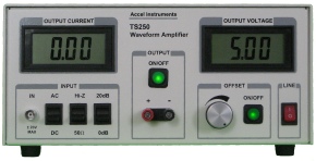
The TS200/TS250 high power function generator amplifier combine with a function generator, can achieve the above requirements and making it ideal for transient response test. The TS200/TS250 can drive up to 6A peak current and it can drive large capacitance. Working with a function generator, the output rise and fall time can be controlled.
Figure 2 shows how to measure line transient response. A function generator generates a square pulse with an adjustable rise and fall time (e.g. 10us). The function generator is connected to the TS200 modulation input. The TS200 output is connected to the device under test (LDO voltage input). The TS200 modulation input is set to AC-

For faster rise time than 10us, it is recommended to keep the LDO input capacitor to minimum (less than 1uF) to allow faster rise and fall time. Use as short cables as possible (less than 12 inches) connecting TS200 output and the DUT. Twist the cables to together to minimize inductance.
To measure the line transient step, connect an oscilloscope probe (CH1) to the LDO input and another probe (CH2) to the LDO output as shown in Figure 2. The transient response is measured at CH2. Figure 3 shows an example of line transient measurement.
Figure 2. LDO line transient response test setup.

Figure 3. LDO line transient response measurement example.

Related Technical Information


Quick Links

Copyright: Line Transient Response
