


Instruments For Testing Your Innovations


Parallel Connect Two TS250 For Higher Current
The TS250 outputs very high current from 1.7A to 6A, depends on the model (see Table 1 below). However, in some test and measurement applications, even higher current is needed. To further increase the output current, two TS250 High-
Each TS250 amplifier must isolate their outputs from one other with a small resistance resistor. The isolation resistors are connected to the positive terminals. The TS250 negative terminals connected together and to the load negative terminal.

Related App Notes
Parallel Connect Three TS250
Parallel Connect Two TS250 with Resonant
Piezoelectric Driver Amplifier
Ultrasonic Amplifier


Quick Links
Table 1. TS250 High-Current Amplifier Selection Guide

Choosing the Resistance Value


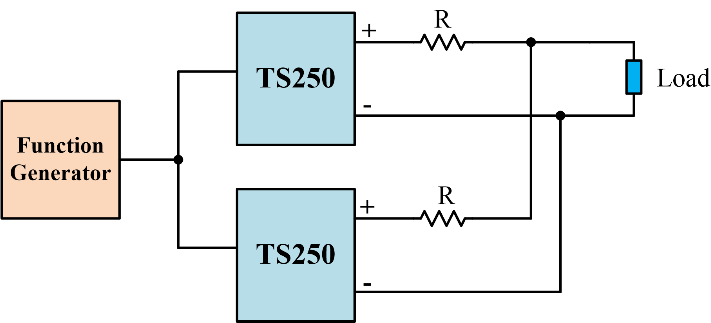
Figure 1. Connect two TS250 high-
The isolation resistance should be chosen as large as needed, but not too large to cause excess voltage drop. The resistance is chosen so that at peak TS250 output current, it will cause a voltage drop of 0.5V. For example, if the peak current from each TS250 is 2.5A, the resistance should be as least 200mOhm.
It is recommended to chose as large resistance possible and still have enough headroom. For example, in a given test application the unit-
Resistor Power Dissipation
At high current, the resistors will dissipate large amount of power. These resistors may get hot. The resistor must be chosen to dissipate the rated power. The power dissipation is calculated by the RMS current square multiply by the resistance.

For high frequency testing, the series resistors should be non-
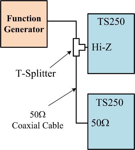
Connecting to Function Generator
The TS250 input is designed to interface with common function generators. Special connection is needed for connecting two TS250 high-
Figure 2. Serially connecting the function generator to two TS250.