


Instruments For Testing Your Innovations


Advance Magnetic Field Calculator
Figure 1. Cross-

Support both solid and Litz wire, calculates AC resistance over frequency and temperature, support resonance technique calculation, and much more.
Coil Inner Diameter: Coil copper inner diameter, excluding plastic bobbin. Note the copper inner diameter is not same as the bobbin inner diameter. Copper inner diameter must be larger than bobbin inner diameter. See Figure 1 for details.
Coil Length: Enter the length of the solenoid or coil. See Figure 1 for details.
Number of Turns: Enter the number of turns in the coil or solenoid.
Coil Current: Enter the coil current. For DC-
Distance From Plastic Surface: If you need to calculate the magnetic field outside of the coil, enter the distance from the bobbin surface.
Distance from the center of the inside of the coil: If you need to calculate the magnetic field intside of the coil, enter the distance from middle of the coil. Figure 2.
Frequency: Enter the solenoid/coil operation frequency (sinewave). For DC, just leave the default 1kHz and use the DC parameters calculated below.
Wire Outer Diameter with Insulation: Enter the overall wire diameter, include insulation.
Strand Diameter: For solid wire, enter copper wire diameter WITHOUT coated insulation. For Litz wire enter the single strand diameter WITHOUT coated insulation. This is the bare copper diameter. This diameter is used to calculate the resistance more accurately.
Number of Strands: For solid wire enter 1. For Litz wire enter the number of strands.
Capacitor Dissipation Factor: Enter resonance capacitor dissipation factor or loss tangent. For example, Polypropylene film capacitor have a dissipation factor of 5x10^-
Plastic Thickness: Bobbin side thickness. You may enter 0 if you want to exclude bobbin in the calculation.
Winding Porosity-
Core Relative Permeability: Enter the core relative permeability constant, k. Enter 1 for air core.
Winding Compact-
Outputs:
Magnetic Field From Plastic Surface: The calculated magnetic field outside the coil using the distance entered above. Valid for air core (permeability = 1) coil only. For coil with a core (permeability > 1), the magnetic field outside the core cannot be calculated accurately.
Magnetic Field From Center: The calculated magnetic field inside the coil using the distance entered above. Magnetic field vs distance is valid for air core (permeability = 1) coil only. For coil with a core (permeability > 1), the magnetic field inside the core is approximately constant. To calculate the magnetic field inside the core, enter 0 for “Distance from the center of the inside of the coil”.
Minimum DC Driver Voltage Required: This is the voltage needed for DC magnetic field.
Coil DC Power Dissipation: This is how much power is dissipated for DC magnetic field.
Coil AC Resistance: This is the resistance at the frequency entered above. AC resistance is dominated by proximity effect and increase exponentially with frequency and winding layer. Reduce the number of winding layers, or reduce the wire diameter, or use Litz wire to reduce the resistance.
Coil AC-
Minimum Coil+Cap AC Driver Voltage Required: This is the minimum voltage amplitude need to drive the coil using resonance technique. For example, 9.8V means you need a coil driver that can output sinewave from -
Minimum Coil Only AC Driver Voltage Required : Information only. Ignore it.
Coil AC Power Dissipation: This is the AC coil power dissipation at the current entered above.
Inductance: Coil inductance in micro-
Resonance Capacitor Capacitance: This is the capacitance needed to form an LC resonant tank. The coil impedance is reduced or canceled using this series resonant capacitor (Figure 5). Click here for more information about series resonant magnetic coil. It is calculated using the coil inductance and the user input frequency. Tip: Generally use Polypropylene film capacitor, especially at higher frequencies. Ceramic capacitor is acceptable if the ESR is low enough and can handle the power dissipation. Class-
Resonance Capacitor Voltage Rating: For resonance technique (Figure 5), this is the minimum capacitance voltage rating. This is the sinewave zero-
Capacitor ESR: Capacitor resistance at the frequency entered above. Tip: Use Polypropylene file capacitor. NPO/C0G ceramic capacitor maybe okay as long as the ESR is low enough and the capacitor can handle power dissipation.
Capacitor Power Dissipation: This is how much power (heat) will be dissipated by the resonance capacitor. Make sure the capacitor can handle the power.
Penetration Ratio: Information only. Proximity effect penetration ratio. Generally keep the ratio less than 0.5.
Skin Depth: Information only. Ignore.
Skin-
Total Impedance: This the magnitude of the coil impedance. It includes both the reactive and resistive components.
Number of Layers: Total number of layers of winding.
Coil Layer Height: Total number of layers adding up to the height or thickness.
Average Inter-
|
Gauge |
Diameter |
|
10 |
2.67716 |
|
11 |
2.39268 |
|
12 |
2.13868 |
|
13 |
1.91516 |
|
14 |
1.7145 |
|
15 |
1.53162 |
|
16 |
1.36652 |
|
18 |
1.09474 |
|
20 |
0.87884 |
|
Gauge |
Diameter |
|
10 |
2.58826 |
|
11 |
2.30378 |
|
12 |
2.05232 |
|
13 |
1.8288 |
|
14 |
1.628 |
|
15 |
1.45034 |
|
16 |
1.29032 |
|
18 |
1.02362 |
|
20 |
0.8128 |
Table 1. Wire gauge diameter with insulation in mm.
Table 2. Gauge diameter without insulation (bare copper) in mm.
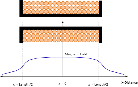
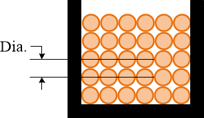
Figure 3. Coil winding spacing factor of one.
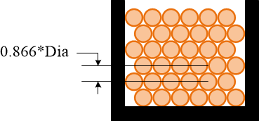
Figure 4. Ideal compact factor. The distance between two layers is 0.866 of diameter.
Figure 2. Calculated magnetic field at distance x from the center.

Figure 5. High-


Figure 6. Dielectric strength reduction over frequency (kHz). Source: UL.
Coil Input Parameters
High-Voltage Safety
-
-
-
-
-
-
-
-
Coil Design Tips
Generally speaking, first priority is to reduce the resonance voltage. That means reduce the inductance. Keep the coil diameter as small possible. The inductance is proportional to the number of turns square. Reduce the number of turns by half will reduce the inductance by a factor of 4. Then increase the current by 2. The magnetic field remains about the same, but the resonance voltage is reduced by 2x.
AC resistance is dominated by proximity effect. Copper wire diameter either too large or too small will increase the resistance. Using the calculator to experiment with the different wire diameter for the lowest resistance. If the resistance is still too high, either use Litz wire or reduce the number of winding layers.
Pay attention to the “inter-
Often time and at high frequency and high current, the coil design can only be one layer. More than one layer is not possible due to too high voltage between two layers. You also need to look at the voltage between two loops. This voltage should not be higher than 500V. The voltage between loops is the resonance voltage divided by the number of loops.
You may use “Super Corona Dope” from MG Chemicals # 4226 to enhance the dielectric strength.
As a reminder, you need to use Polypropylene Film capacitor in most cases. The KEM R74 and R76 series capacitors are available from Digi-
Here are the steps for choosing capacitors:
1) Us our online calculator to calculate the resonance voltage and capacitor.
2) Choose capacitor with high AC voltage. For example 700VAC, which is the RMS voltage. So the peak voltage is 989V.
3) Choose capacitance that does not derate at your maximum test frequency.
4) Connect capacitors in series to meet the resonance voltage. For example, if the resonance voltage is 5000V, you need to connect 6 capacitors in series. This is one string of capacitors.
5) Connect as many strings of capacitors as need to meet the required resonance capacitance.
Making the capacitor bank:
1) Use a breakable plastic tray, place the capacitors in the tray with the electrical leads (pins) point upward in an array. i.e. 6 x 5, 6 caps in series and 5 strings.
a. Recommended to use 3D printer to print a thin plastic tray.
2) Use the "Super Corona Dope" from MG Chemicals # 4226 to glue all of the capacitor together.
3) Wait for the glue to dry.
4) Gently bent the adjacent (series) leads (pin) toward each other.
5) Use soldering iron to solder the adjacent leads
6) Use a 18 AWG tinted copper wire to solder the input and output of the capacitor network.
Resonance Capacitor
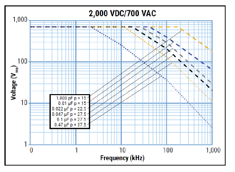
Figure 7. Capacitor voltage derating over frequency.