Helmholtz coil is driven by a waveform amplifier to create high frequency magnetic field. High frequency Helmholtz field is produced by high current waveform amplifier.
Technical Info Download Contact

Instruments For Testing Your Innovations

AC Helmholtz coil produces high frequency magnetic field by the TS250 high current amplifier. Alternating Helmholtz coils are driven by a high-frequency and high-current amplifier.

AC Helmholtz Coil Magnetic Field

Helmholtz Coil Design Calculations

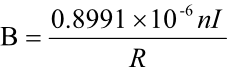
Use the below equation to calculate the Helmholtz field.


                                                                             Eq. 1


B = field in Tesla      

n = number of turns in a coil      

I  = current in amperes   

R = coil radius in meters

Helmholtz coil design using two high-frequency coils produce uniform electromagnetic field for lab experiments.

Very high frequency AC Helmholtz coils are frequently used to create even but time varying high-frequency magnetic field for a number of purposes such as magnetic field calibration, magnetic susceptibility, and scientific experiment. A Helmholtz coil driver at very high frequency is necessary for the production of the required magnetic field. The magnetic field intensity is proportional to electrical current which means that high current is required for the generation of a high magnetic field. At the same time, high impedance is obtained at high-frequency from the impedance of the coil. For a specified driver voltage amplitude, the coil current is inversely relative to the coil impedance. As a result, current and frequency will be the two opposing factors which affect magnetic field. It is incredibly difficult to achieve high-frequency magnetic field. This article talks about three techniques to create high magnetic field for high-frequency Helmholtz coils.

Introduction

Helmholtz coils, titled after the German physicist Hermann von Helmholtz, comprise of two identical magnetic coils placed in parallel with their centers aligned in the same axis just like a mirror image as exhibited in Figure One. A highly even magnetic field in a 3-dimension three dimensional space is created within the coils when electrical current goes through the high-frequency Helmholtz coils in the identical direction. These Helmholtz coils are generally utilized for measurements and calibration, for cancelling the ambient (earth's) magnetic field, and as a magnetic field for susceptibility testing of electronic devices.

Very high frequency Helmholtz Coils Basic
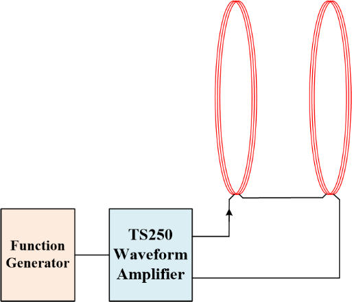
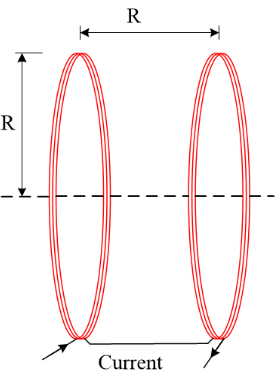
Figure 1. Single-axis high frequency Helmholtz coils consist of a set of coils with radius R. They are separated by a distance equal to R.

Very high frequency Helmholtz coils are constructed by two coils. The 2 magnetic coils are designed to be identical so even magnetic field is achieved when the coil radius is equal to the separation distance. The 2 coils are connected in series such that identical current that is fed to both results in the creation of two identical magnetic fields. The 2 added fields accomplished uniform magnetic field in a cylindrical three dimensional space which was in the center of the two parallel coils. This cylindrical-shaped volume's even field is approximately equal to 25% of coil radius (R) and it has a length equal to fifty% of the spacing between the two coils. Very high frequency Helmholtz coils come in 1, two, or three axes. Magnetic coils with multi-axes generate magnetic fields in any direction in the three dimensions within the Helmholtz pair. Circular very high frequency Helmholtz coils are the most common type of high-frequency Helmholtz coils. Square Helmholtz coils also are commonly available.

Design and Construction of Helmholtz Coils

Each Helmholtz coil is made from loops of electrical (copper) wires. When current is passing throughit, magnetic field is generated. The current is relative to the magnetic field density. The Helmholtz coils magnetic field equation is shown below.

Magnetic Field Calculation of Helmholtz Coils

From Equation 1, small radius coil creates higher magnetic field strength. Also the more number of turns in each coil, the greater the magnetic field.

Helmholtz magnetic field is created either using Alternating current or DC current. A good number of Helmholtz coils applications are static (constant) magnetic fields and these fields utilize DC current. Certain applications require non-static magnetic fields at very high frequencies (khz to MHz). An illustration of this such an application is a scientific research. This article is primarily discussing high-frequency Helmholtz coils.

High frequency Helmholtz Coils Model

Figure 2. Circuit model of 2 Helmholtz coils connected in series.

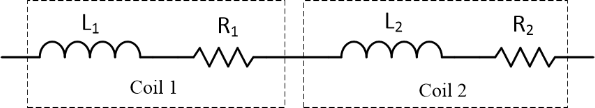
A set of high frequency coils can be modeled as shown in Figure 2. Each coil can be modeled like a parasitic resistor and an ideal inductor in series. The parasitic resistor resistance is frequently small. For most very high frequency Helmholtz coils applications where the testing frequency is far below the self-resonant frequency, this model is satisfactory.

If the Helmholtz coil testing frequency is close enough to its self-resonant frequency, the circuit model must also take into account its parasitic capacitances (CP1 and CP2). The parasitic capacitors are parallel to each inductor and resistor in series as portrayed in Figure 3.

Figure 3. Very high frequency Helmholtz coils are represented by 2 series connected LCR circuits.

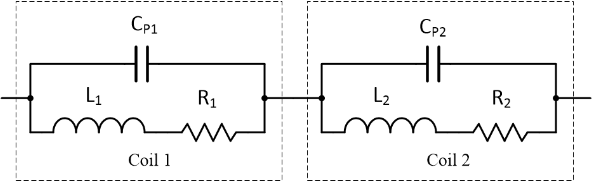
The parasitic capacitance and inductance produced a self-resonant frequency. A few small amount of variations between the coils are expectedalthough the coils have been built to be as closely matched as possible. A parasitic capacitance and series resistance is contained by each coil. The coil inductance along with the parasitic capacitance produced a self-resonant frequency.

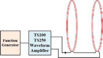
Very high frequency Helmholtz coils may be series connected as shown in Figure 2 or in parallel as shown in Figure 4. Series connection allows the same current flow through the 2 magnetic coils. Generally, series connection allows for the greatest current and therefore the highest possible magnetic field. However, because 2 coils are in series, the total reactance is also doubled. Higher reactance could require higher driver amplifier voltage. The reactance can be reduced through the use of the resonant techniques explained below.

High frequency Helmholtz Coils Connections

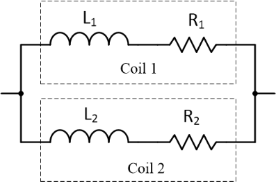
Figure 4. Helmholtz coils parallel connected.

Connecting Helmholtz coils in parallel has the benefit of a reduced reactance. In fact, the reactance is reduced by one-half, but the current is also cut in half (current is separated into 2). A lower magnetic field is what results from this. A connected in parallel is okay if the following conditions are met: low reactance is necessary and the required magnetic field intensity is reached at half the current. An example of this is the case of the low-voltage amplifier driver. More information about Helmholtz coil impedance are in the Direct Drive Method section below.

There are 3 ways that very high frequency AC magnetic field can be generated. The very first method that will be discussed is the direct drive method. This is the method that is the most simple manner for magnetic field to be produced for testing. Altering the magnetic field and frequency under test is incredibly easy. The second method is series-resonant method. This is a powerful method to create very high magnetic field along with very high frequencies to the order of hundreds of kilohertz or even Megahertz. A new current-magnified resonant is the third method. The greatest magnetic field intensity is created through the use of this method. The below sections will describe each method.

Driving High-frequency Helmholtz Coils

If the coils are low inductance or the study is not high-frequency or both, the Helmholtz coils may be driven directly using a waveform amplifier driver including the TS250 Waveform Amplifier from Accel Instruments. Because of low inductance or not high-frequency, the coil's reactance is low enough to be driven by an amplifier directly. This is shown in Figure 5 and Figure 6.

Direct Drive Technique

Figure 5. TS250 Waveform Amplifier drives a set of Helmholtz coils.

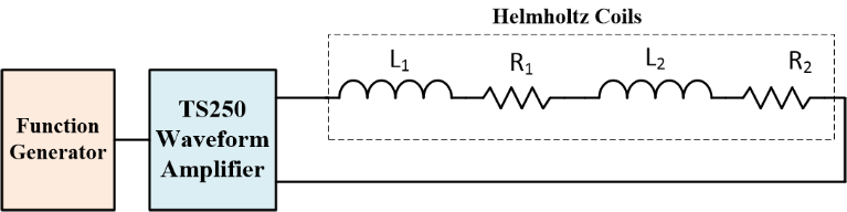
Figure 6. Equivalent circuit of a Waveform Amplifier directly driving a set of series connected Helmholtz coils.