


Amplifier common-mode rejection ratio (CMRR) is a specification of the amplifier’s ability to reject common-mode signals (noise) at the input that can propagated to the output. For example, if the op-amp CMRR spec is 60dB and its gain is 40dB, a 10mVpp common-mode noise at the input will resulted in 1mVpp noise at the output (10mV/1000*100 = 1mV). Examples of common-mode signals are noise in the system, ground noise (ground bounce), coupling from adjacent lines, etc.
CMRR = 20log(Gain*Vin/Vout) (CMRR number is positive in dB)
Common-mode rejection is measured by injecting a sinewave into the op-amp’s common-mode input and measure the signal at the amplifier’s output. Figure 1 shows the CMRR test setup. The amplifier’s positive and negative terminals are shorted together to make the differential mode zero. Sinewave is injected to the positive and negative terminals together.
( a )
( b )
Figure 1. CMRR measurement setup for amplifier. (a) Calibration setup, (b) CMRR setup.
Typically CMRR measurement is done by using a network analyzer (see table 1). Using the setup in Figure 1, the network analyzer Source output is applied to the TS200 Modulated Power Supply input. The TS200 output is connected to the amplifier’s common-mode input. Set the TS200 modulation input to AC-coupled. Adjust the DC Offset knob until the output DC voltage reaches the desired common-mode voltage (i.e. ½ VCC). Typically for CMRR measurement, the supply ripple amplitude is about 200mVpp.
First the network analyzer and the TS200 need to be calibrated. Figure 1a shows the calibration setup. The network analyzer input-A and input-B are connected together at one point on the DUT board near the op amp input. Set the network analyzer to calibration mode and sweep over the frequency range (i.e. 100Hz to 100kHz) to be measured. Save the calibration data for later use. Refer the network analyzer manual for detailed calibration setup.
After calibration, amplifier CMRR measurement setup is shown Figure 1b. The network analyzer input-B is moved to the amplifier output while keeping input-A at the input. Again sweep the network analyzer over the desired frequency range. You may refer to the network analyzer manual for details. For thoroughness, op amp CMRR should be tested over the entire range of specified common-mode range (i.e. ~0V to ~VCC).
How to Measure Op-Amp CMRR
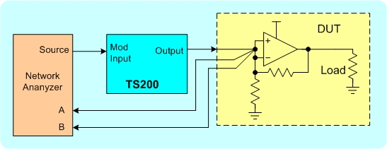
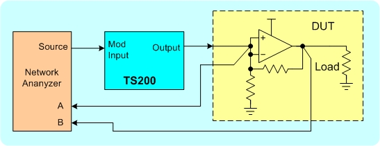
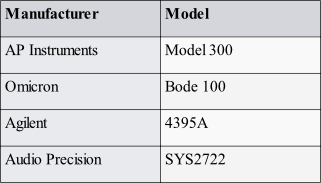
Table 1. List of network analyzers


